Type 3 and Type 4 are Here!
October 4, 2018 / General, Standard and Certification, Industrial Networks
Last week the IEEE 802.3bt standard for Type 3 and Type 4 PoE was finally ratified! While we’ve been talking about these higher levels of PoE for quite some time, now that they are finally an approved standard, we thought it was a good time to clear the air on PoE types, classes, and certification, as well as provide a refresher on our specialty—testing.
Type 3 PoE delivers 60W from the power sourcing equipment (PSE) for up to 51W input power at the powered device (PD) and Type 4 PoE delivers 90W from the PSE for up to 73W input power at the PD. Unlike previous Type 1 (15W) and Type 2 (30W) PoE that use only two pairs to deliver power, these two new PoE levels utilize all four pairs of a twisted-pair cable (which is why you often hear 802.3bt referred to as four-pair PoE). These higher levels of power mean that PoE can now be used to power everything from digital signage and advanced pan-tilt-zoom cameras, to LED lights and even desktop computers.
A Class System
IEEE 802.3 PoE assigns classes to a PoE system, whereby the class is determined by the lowest common power level that can be supported by both the PSE and PD. This is achieved by the PSE detecting the power requirements of the PD using Link Layer Discovery Protocol (LLDP), which essentially analyzes bi-directional data packets between the PSE and the PD.
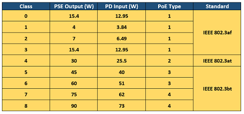
The various classes range from 0 to 8 with Type 1 and Type 2 PoE encompassing Class 0 through Class 4, which covers input power at the PD ranging from 12.95W to 25.5W. Type 3 includes Class 5 (up to 40W at the PD) and Class 6 (up to 51W at the PD), and Type 4 includes Class 7 (up to 62W at the PD) and Class 8 (up to 73W at the PD). Why exactly do we have a class system?
The main reason for a class system to allow power requirements to be negotiated for better management of the PSE’s power budget. For example, if the PSE is Class 6, but the PD is only Class 5, the system is classified as Class 5 and the PSE can set the maximum power delivered to match the requirements of the device rather than putting out more power than is required.
Certification Can Help
Amidst all this PoE talk circulating our industry, you may have also heard about PoE certification through the Ethernet Alliance. The Ethernet Alliance PoE CertificationProgram was developed to help minimize confusion in the market by testing and validating specific PoE equipment to ensure interoperatbility and compliance with IEEE 802.3 PoE standards. Afterall, PoE is just a name that anyone can use to describe a device or a piece of equipment—even proprietary products that are not standards compliant.
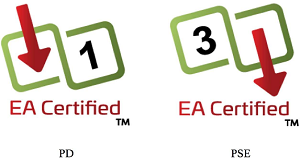
Any company can submit a product to the Ethernet Alliance for certification, and once certified the product is included in a public registry. While more commonly seen for PSE rather than than PDs, an Ethernet Alliance official logo on certified products indicates compliance, identifies whether the product is considered PSE or a PD, and specifies the maximum power either supplied or consumed by the product.
The logo itself is pretty easy to understand—the red arrows indicate the directional flow of power (either receiving or sending) to denote PSE or PD and the number inside the box indicates the class so you know the maximum power (so in hindsight, if you’re going by the logo, knowing the classes is a good thing).
Testing Refresher
We of course can’t talk about the ratification of Type 3 and Type 4 without talking about testing. In a PoE system, power is transmitted by applying a common-mode voltage on the two pairs—meaning the current is evenly split between the two conductors. For this to happen, the DC resistance of each conductor in the pair must be balanced (equal), and any difference is known as DC resistance unbalance. Too much unbalance can distort data signals, causing bit errors, retransmits and even nonfunctioning data links.
With Type 3 and Type 4 PoE now delivering power over all four pairs, it’s no longer just the DC resistance unbalance on each pair you need to worry about. Excessive DC resistance unbalance between multiple pairs can also wreak havoc on your PoE systems. While you may see a DC resistance unbalance specification on a vendor’s cable, inconsistent terminations can also cause DC resistance so field testing for this parameter is the only way you can rest assured that your PoE system is up to snuff.
Fluke Networks’ DSX CableAnalyzer™ Series of Copper Cable Certifiers quickly and easily tests DC resistance unbalance within a pair and between pairs. Download the white paper here to learn more.
最新报道 查看全部 >
什么是光纤?这里有一份指南
2024-03-20
网络和线缆测试终极指南
2024-03-13
选择绞合线缆还是实心线缆
2024-03-06
Fluke CableIQ™ 电缆鉴定测试仪与 LinkIQ™ 电缆 + 网络测试仪比较
2023-06-13
什么是回波损耗?
2023-02-14
布线认证比以往任何时候都更加重要的三个原因
2023-01-05
更多大众报道 查看全部 >
什么是光纤?这里有一份指南
2024-03-20
网络和线缆测试终极指南
2024-03-13
选择绞合线缆还是实心线缆
2024-03-06
如何延续 Versiv™ 投资的价值
2023-12-21
测试 MPTL 时正确方法是什么?
2023-08-22
承包商表示不值得冒逃避认证的风险
2023-07-06


©2006-2021 Fluke Corporation。保留所有权利。
RM2011, 20/F, SCITECH Tower, 22 Jianguomenwai Avenue, Chaoyang District, Beijing, China
地址:北京市朝阳区建国门外大街22号赛特大厦20层2011室
联系电话:400-8103435
沪ICP备11037028号-15![]()