DC Resistance Unbalance within a pair - DSX CableAnalyzer
Resistance Unbalance is a measure of the difference in resistance between the two conductors in a cabling system. This is different to the Resistance measurement normally found in field testers, also known as DC Loop Resistance, but often abbreviated to Resistance.
In the example above, the DC Resistance is measured on each conductor. The difference (Resistance Unbalance) was 0.02 Ω (1.87 Ω - 1.85 Ω).
The DC Loop Resistance is the sum of the two conductors, 3.7 Ω (1.87 Ω + 1.85 Ω) rounded to one decimal place on the DSX CableAnalyzer.
It is something you should watch out for if you intend to implement Power over Ethernet (PoE) on your network in accordance with IEEE 802.3af, IEEE 802.3at or IEEE 802.3bt. Examples of such implementations include IP telephones, wireless access points, building automation and security devices like network (IP) cameras.
Resistance unbalance results in current imbalance in the cabling channel that could cause saturation in the power-sourcing equipment (PSE) transformers. In English, it may not deliver the PoE you need.
Field testing standards such as ANSI/TIA-1152 and IEC 61935-1 do not require this as a field measurement. However, you will find test limits in ANSI/TIA-568-C.2, ISO/IEC 11801:2010 and IEEE for Resistance Unbalance. So why no field test requirement? Until now, there was no field tester that could do this, so it was left as a laboratory measurement only. That is no longer the case with the DSX CableAnalyzer.
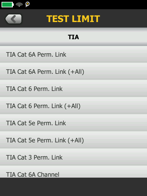
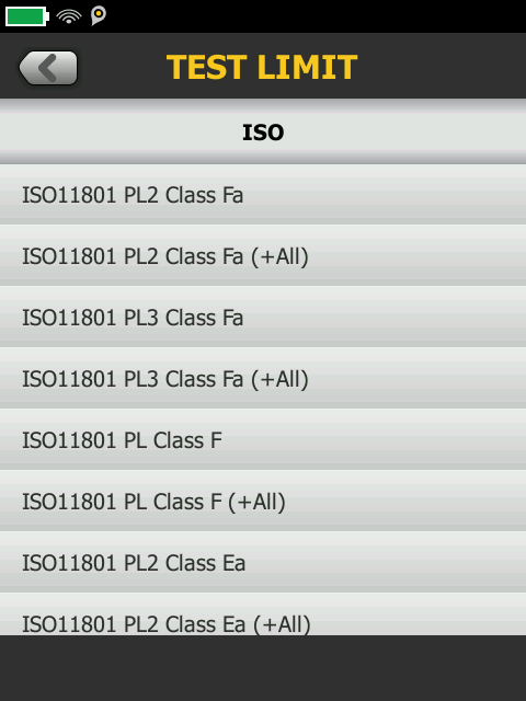
If you want Resistance Unbalanced to be measured, select a test limit on your DSX CableAnalyzer that has a suffix of (+All):