Certifying Singlemode MPO links with OptiFiber Pro
This article describes a method for certifying Singlemode links with 12 fiber MPO connectors at each end using the OptiFiber Pro.
You will need:
- OFP-100-S or OFP-100-Q OTDR module
- A short, 30 cm, SC/UPC to LC/APC source port protector cord (optional)
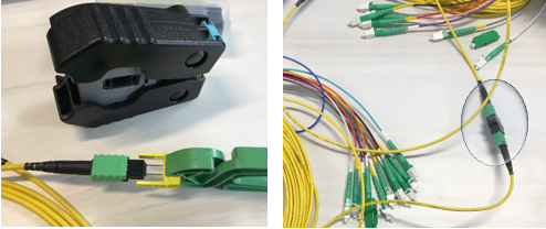
- Qty (2) 30 Meter 12 fiber SM MTP/MPO to LC/APC break out cable with capability to change the gender of connectors (pinned, unpinned)
- Duplex LC bulkhead adapters (Singlemode)
- Qty (2) ADP-MPO-A MPO adapter for SM APC
Additionally, fiber endface inspection is critical for this method to work. Without inspection, you may end up with pessimistic results. Inspection includes both the end faces of the MPO and LC connectors. MPO adapter tips are available for the USB FI-1000 FiberInspector, which attaches to your Versiv.
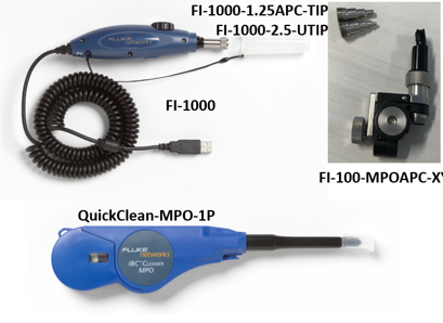
- Inspect all fiber test cord endfaces before inserting them. If clean, do nothing; if dirty, clean them and inspect them again. Repeat as necessary.
-
Confirm test limits with your cabling vendor/consultant. For this test, we are using ANSI/TIA-568.3-E
-
Limits with an added reflectance requirement of -55 dB. Reflectance can be an issue with higher speed connections. It is noise and can lead to CRC/FCS errors.
-
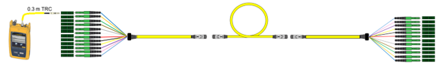
Connect 30 cm Port Protector cord to break out cable. This is optional and is only to protect the source port of the OTDR from contact dirt or damage from multiple insertions

-
Connect two 30 meter break out cables to each other. You may need to change the gender of one of the cords to do this. One MPO/MTP connector must be pinned and the other unpinned to get proper alignment.
-
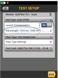
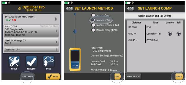
Set Launch Compensation to “On” and be sure the unit is configured for two wavelengths. The default is to work with two wavelengths and we will do this. Even though many applications only run at one wavelength, by checking two wavelengths, we can check the fiber for any macrobends or cracks. These show up with a different attenuation level. Longer wavelengths, like 1550 and 1625, are more susceptible to the bend so they will show it with more attenuation than shorter wavelengths like 1310.
-
Set Launch Compensation Launch + Tail. Save.
-
Disconnect the launch and receive break out cords, reset the pins as needed, and connect as below.
-
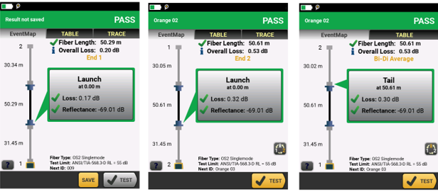
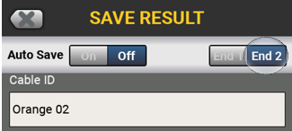
Run the test and save the test results as "end one."
-
When you have finished, go to the other end of the cable, leave the launch and receive fibers attached, and test from the other end. Save these test results as “end two.”
OptiFiber Pro will join the two test results together and give you the bi-directional average of the loss values for the link on the tester. This way assures that you have compensated for any mismatch in the backscatter co-efficient between the break out cords and the links under test