Anixter’s New Utility Grade Infrastructure
November 30, 2019 / General, Standard and Certification, Industrial Networks
Fluke Networks has announced support for Anixter’s Utility Grade Infrastructure. That means that Anixter Certified UTG Integrators can use the DSX CableAnalyzer to certify their installations. We thought we’d explore the UTG program and what it offers the marketplace.
Everybody knows about Category-rated cabling, but you would have to have been in the industry in the late 80’s and early 90’s to remember that Anixter was one of the driving forces behind the development of the concept. Since those days of Category 3 and 5, the industry has moved up the speed curve, with Cat 6A supporting 10 Gig up to 100 meters and Cat 8 someday supporting 40 Gig up to 30 meters. While advances in data rates are critical, new challenges have emerged: Power over Ethernet (PoE) and cable lengths.
Consider the situation where a customer is installing a new PoE-powered camera on the outside of the facility. In this case, the cabling run to the nearest telecommunications closet is 130 meters. A design based on current standards would require the building of a telecommunications closet (TC) closer to the camera. This would require a cable run to the new TC, plus a panel, rack and associated hardware. The new TC may also require AC power, a door with a lock and a smoke detector – a considerable expense to support a single device.
With the ability to support 100 Mbps bandwidth and 30 W of PoE over runs of up to 150 meters, UTG cabling could handle this requirement without the cost of the TC. UTG comes in two flavors: UTG10, which is based on Cat 6 performance, and UTG20, based on Cat 6A. Anixter worked with Belden, CommScope, and Fluke Networks to define the parameters of the cabling, and then with Underwriters Laboratories to ensure its ability to deliver the specified performance.
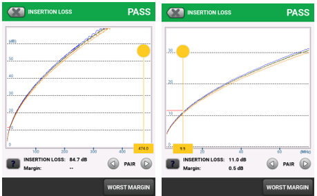
So how do you get cabling to work at these long lengths? The loss on a cable is proportional to its length. The left hand DSX CableAnalyzer screen shot shows the insertion loss for a 185 m cable. Looking carefully, you can see that the loss at 300 MHz is over 60 dB – meaning that the signal arriving at the receiver would be less than 0.1% of the voltage of the signal transmitted – far too low to be of any use. However, in the rightmost shot shows a close-up view of that same cable at 10 MHz where the loss is 11 dB. So a 10 MHz signal arriving at the far end would be 28% of the input signal – strong enough for reliable operation. As a result, UTG cabling can run 10 Mbps Ethernet up to 185 meters and 100 Mbps up to 150.
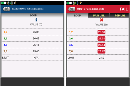
UTG cabling ensures extended PoE performance (up to 30 watts at 150 meters) by requiring field testing of key resistance parameters in installed links. While both the TIA and IEEE require cabling to meet resistance requirements, these measurements are not required for field testing. While Fluke Networks recommends these tests for installed runs supporting PoE, Anixter has gone further and requires them for their UTG certification program. The two screen shoots at right show the difference. The leftmost one shows a cable passing TIA Permanent Link tests where the Loop Resistance is shown as informative only. The rightmost test of the same cable fails the UTG 10 limits, where the Loop Resistance test results are compared against the UTG limit of 21 Ω.
Anixter UTG Certified Integrators can get the complete set of UTG limits for the DSX-5000 or DSX-8000 CableAnalyzer by contacting their Anixter Channel Sales Representative or visiting https://www.anixter.com/solutions/utg/certification.