What You Should Know About VSFF Connectors

2025 年 5 月 27 日 / General, Installation and testing, Best Practices

Fiber density is exploding as data centers pack in more servers, switches, and storage to handle massive data and emerging high-performance computing (HPC) applications like AI, with clusters that can encompass hundreds or even thousands of interconnected graphics processing units (GPUs). New very small form factor (VSFF) connectors are emerging as potential game-changers to maximize space in these high-density environments. Let’s look at how these VSFF connectors differ from traditional fiber connectors and the various applications where they’re used.

VSFF Connectors Are Designed for Density

Fiber technicians today are familiar with duplex connectors such as the 2.5mm SC, ST, and FC fiber connectors and the widely deployed 1.25mm small form factor LC connector. Those working in data centers also use multi-fiber push-on (MPO) connectors, which bundle multiple fibers for high-speed parallel optic applications.

But as data centers grow in complexity and density, traditional connectors struggle to keep up. Enter the VSFF connector, offering significant space savings in dense infrastructure environments. VSFF connectors are the next generation of fiber technology. They are engineered to maximize port density for modern transceivers like QSFP-DD and OSFP. A number of VSFF connectors have hit the market over the past few years, including CS, SN, and MDC duplex connectors, and SN-MT and MMC multi-fiber connectors. Let’s consider each of these variants.

CS Duplex Connector: Small Size, Big Performance

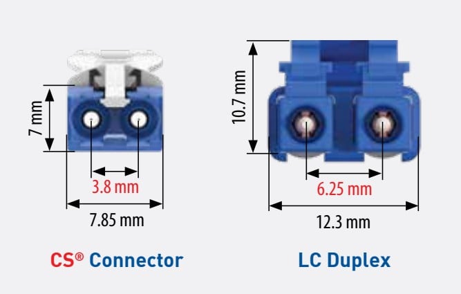
Introduced by Senko in 2018, the duplex CS connector offers 40% more density than the LC connector. While the CS maintains the same proven 1.25mm ferrule as the LC, the two fibers are spaced at just 3.8mm, compared to the LC’s 6.25mm. The smaller spacing gives the CS connector an overall size of 7.85mm X 5.3mm, compared to 13 mm X 10.7 mm for the LC. To give you a sense of the size difference, CS connectors allow for 144 duplex ports in a 1U patch panel, while the highest-density LC patch panels only support 96 duplex ports.

Diagram comparing the CS duplex connector to the LC duplex connector.

The VSFF CS duplex connector is 40% smaller than the LC duplex connector.

Key CS connector features:

  • • Push/pull tab for easy insertion and removal
  • • Available in UPC and APC styles for both multimode and single mode fiber
  • • Maximum insertion loss of 0.15dB for low-loss single mode and multimode
  • • Supports 400G dual WDM applications via Twin CS configuration in QSFP-DD modules

The CS connector was designed primarily to fit two CS connectors in a QSFP-DD transceiver module. Only one LC fits into a QSFP-DD module, limiting LCs to single wavelength division multiplexing (WDM) applications. Achieving 400 Gig with the duplex LC requires 8 wavelengths per fiber (each transmitting or receiving at 50 Gb/s), which increases transceiver costs.

In contrast, two duplex CS connectors in a QSFP-DD (called a Twin CS) support dual WDM 400 Gig applications (2X200 Gig), using 4 wavelengths per fiber — reducing transceiver costs and enabling higher switch port density. Senko licenses the CS connector, so you might see them offered by your cable and connectivity manufacturer.

Diagram comparing the CS duplex connector to the LC duplex connector in a 400G WDM application.

Two VSFF CS duplex connectors fit into a QSFP-DD transceiver to reduce the number of wavelengths and costs. 来源:Senko.

SN Duplex Connector: Optimized for Hyperscale Interconnects

More recently, Senko introduced the SN VSFF duplex connector to meet increasing data center speeds and further reduce costs. Designed primarily for demanding hyperscale data center interconnects, the SN connector maintains proven 1.25mm ferrule technology but spaces the fibers vertically at just 3.1mm, reducing connector width to just 3.85mm for 3 times the density of the LC.

Diagram comparing the SN duplex connector to the CS and LC duplex connectors.

The VSFF SN duplex connector positions fibers vertically to significantly reduce connector width. 来源:Senko.

Key SN connector features:

  • • Fits 4 SN connectors per QSFP-DD module
  • • Excellent for 4x100G breakout links from a single 400G port
  • • Eliminates the need for fan-out cables or transition cassettes
  • • Uses a push-pull boot with the same 1.25mm ferrule

The SN is designed to fit four connectors in a QSFP-DD transceiver, making it ideal for transitioning from 8-fiber applications to duplex applications, such as 4X100 Gig breakout deployments. Like the CS connector, the SN features a push/pull tab for easy insertion and removal, offers superior insertion loss, and can be licensed to cable and connectivity manufacturers.

Image showing four SN duplex connectors in a single 8-fiber transceiver.

Fitting four SN duplex connectors into a single transceiver is a cost-effective option for breakout applications. 来源:Senko.

MDC Duplex Connector: the Competitive Option

Technology developments in the data center industry bring competition, so it’s no surprise that US Conec also introduced a VSFF duplex connector: the MDC (Mini Duplex Connector). Slightly smaller than the SN, the MDC also uses the proven 1.25mm ferrule with vertically positioned fibers. However, the MDC and SN connectors are not compatible — don’t try plugging one into the other’s transceiver interface or patch panel port.

Image showing four SN duplex connectors in a single 8-fiber transceiver.

Slightly smaller than the SN connector, MDC duplex connectors by US Conec fit into a single transceiver and provide another option for breakout applications. 来源:US Conec.

Key MDC connector features:

  • • Four MDCs fit into a single QSFP-DD module
  • • Competes directly with SN in hyperscale data center deployments
  • • Licensed to cabling manufacturers, like the MTP (their version of the MPO)
  • • Not cross-compatible with SN connectors

Multi-Fiber VSFF Connectors: SN-MT and MMC

Ultra high-speed 800 Gig parallel fiber optic applications utilize a 16-fiber MPO connector (MPO-16) with 8 fibers transmitting and 8 receiving at 100 Gb/s per lane. Traditional MPO-16 connectors house 16 fibers centered in a single row and spaced 5.3mm apart between two alignment pins. The overall connector measures 12.4mm x 8.2mm, allowing roughly 80 MPO-16 connectors to fit within a 1U patch panel. For future 1.6 Terabit applications, this solution uses dual MPO-16 connectors to maintain lane integrity at 100 Gb/s per fiber.

To address density demands today and tomorrow, Senko and US Conec both introduced VSFF 16-fiber connectors:

  • • SN-MT – based on Senko’s SN form factor, available in 8- and 16-fiber variants
  • • MMC – US Conec’s alternative, available in 12-, 16-, and 24-fiber variants
  • • Both connectors use pins for alignment and user-friendly push/pull boots for easy access

These connectors both use the same vertical stacking approach of duplex SN and MDC connectors, reducing connector housing width to provide nearly three times the density of traditional MPOs. To put the size difference into context, 216 SN-MT or MMC connectors can fit in the same space as 80 traditional MPO-16 connectors.

Side-by-side comparison images of traditional and VSFF 16-fiber MPO connectors.

New VSFF 16-fiber MPO connectors are nearly one-third the size of traditional 16-fiber MPO connectors, offering improved density in high-performance computing MPO connector structures. 来源:Senko 和 US Conec。

Hyperscale data center equipment providers and switch manufacturers are already developing switches with pluggable transceivers that accommodate SN-MT and MMC connectors for high-performance computing (HPC) applications. The smaller size of the SN-MT and MMC makes pulling preterminated trunks through pathways much easier. SN-MT and MMC connectors are also ideal as board-mounted connectors in on-board optics and co-packaged optics that bring the electro-optic conversion process closer to the switch’s application microchip.

How to Test VSFF Connectors

While large hyperscale and cloud data centers are just starting to use VSFF connectors for high-speed interconnects and HPC environments, adoption will likely grow over the next decade as more data centers migrate to 800 Gig. Fluke Networks is keeping an eye on market adoption for these new connector variants and will develop VSFF interfaces for our fiber optic test and certification solutions to meet demand. These solutions will allow for a 1-jumper reference, which provides the least uncertainty in the measurement.

In the meantime, testing VSFF connectors on patch cords or installed cabling may require the 3-jumper method, using breakout test reference cords on either side of the cabling under test. For details, check out the Fluke Networks Knowledge Base on using the 3-jumper method for testing duplex VSFF connectors.

Testing multi-fiber SN-MT or MMC connectors today also requires the 3-jumper method, using a Y breakout cable with a 16- or 24-fiber VSFF connector on one end and two 8- or 12-fiber MPOs on the other, depending on the connector variant. In this scenario, both legs need to be tested and added together to test the overall link loss.

Help with Testing VSFF Connectors

If you’re working with VSFF connectors and aren’t sure how to test them, our experts at the Fluke Technical Assistance Center (TAC) can help. They will help you determine the right fiber test solution and testing method for your application.