需避免的 10 大电缆测试错误
2025 年 6 月 5 日 / 通用、安装与测试、升级与故障排除
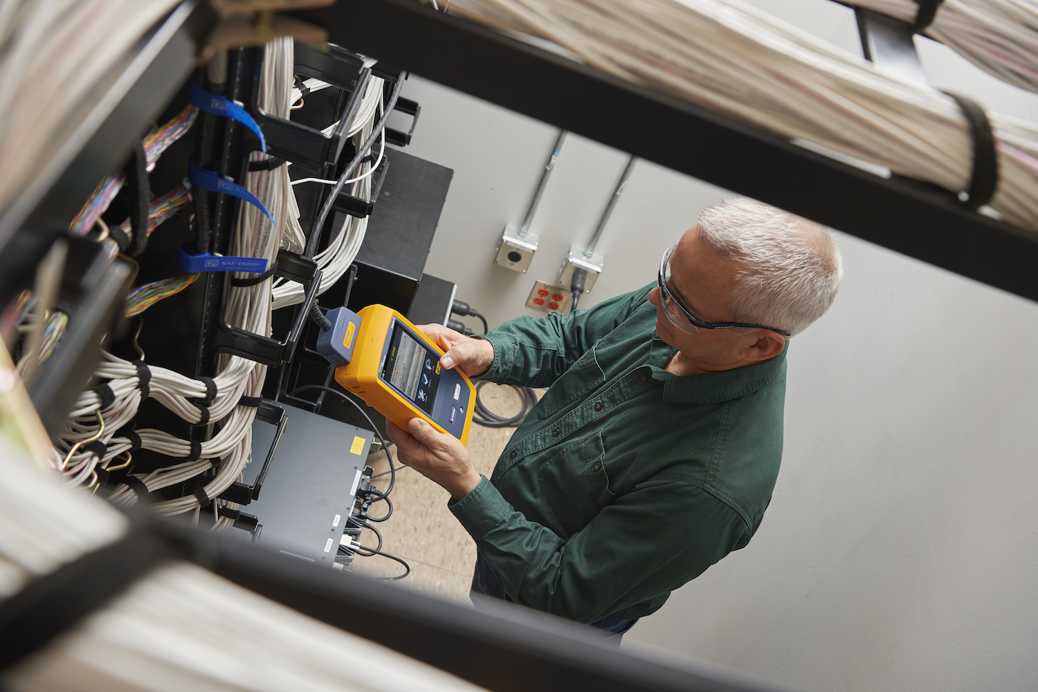
负责安装、测试和认证网络布线设备的专业人员深知符合标准性能参数以及确保应用支持的重要性;然而,即便是最优秀的人员也可能犯错,这些错误会对企业盈利和客户满意度产生不利影响。以下是测试网络布线系统时应避免的 10 大错误。
#1:忽视就测试参数达成一致
当涉及铜缆布线设备认证时,诸如 ANSI/TIA-568.2 和 ISO/IEC 11801 等行业标准规定了基本性能参数,包括:
- • 插入损耗 (IL)
- • 回波损耗 (RL)
- • 近端串扰和远端串扰(NEXT 和 FEXT)
- • 对于 6A 类电缆,还需进行外部串扰测试,因为它是一个关键性能参数,会影响 10GBASE-T 的运行能力。
现场测试还可包括额外的可选平衡参数。
- • 直流电阻不平衡计算线对内和线对间导体的直流电阻差异,表明对以太网供电 (PoE) 的支持情况。
- • 横向变换损耗 (TCL) 和等水平横向变换传输损耗 (ELTCTL) 测量线对内的共模信号,表明抗噪声的平衡性能(包括外部串扰)。
DSX CableAnalyzer™ 认证测试仪的默认测试限制是 (+PoE),其中包括直流电阻不平衡。选择 (+All) 测试限制会增加 TCL 和 ELTCTL 参数。
从技术上讲,认证铜缆系统需要按照应用的行业标准所规定的参数进行测试,对于 6A 类电缆,这些参数包括外部串扰。然而,最终测试的参数取决于客户的项目规格,无论标准如何规定或行业专家如何建议。如果规格要求提供电缆设备保修,您还必须测试电缆制造商要求的参数。
您肯定希望避免因首次遗漏某些参数而重新测试所带来的时间和费用成本。这就是为什么与客户和电缆制造商提前就所有测试参数达成一致至关重要。这也有助于您估算项目成本并为工作做好准备,包括确保您的测试仪能够测试指定的所有参数,特别是像直流电阻不平衡、TCL 和 ELTCTL 等新参数。值得庆幸的是,这些参数可以用 Fluke Networks DSX CableAnalyzer™ 认证测试仪进行测试。

提前就测试达成一致对于光纤测试同样适用。确保您、您的客户和电缆制造商在进行 1 级或 2 级光纤测试方面达成共识,这样您就能知道除了光损耗测试仪 (OLTS) 之外,是否还需要光时域反射计 (OTDR)。
- • 使用 OLTS 进行 1 级测试可提供光纤链路长度上最准确的插入损耗测量,这是行业标准要求的。
- • 使用 OTDR 进行 2 级测试是扩展测试,用于表征光纤链路上各个熔接点和连接器的插入损耗和反射率。请注意,如果您和客户商定进行 2 级测试,仍需使用 OLTS 以确保符合应用要求,因为它能准确测量总插入损耗。
#2:未就临界测试结果达成一致
作为安装人员,您希望符合标准的电缆的每次测试都能通过。然而,从安装操作到组件质量,再到测试仪本身等各种因素,都可能使链路的测试结果处于临界通过区域,即结果更接近测试限制,而非现场测试仪制造商公布的精度范围。根据 TIA 和 ISO/IEC 标准,任何临界通过结果仍被视为通过且符合要求。这些标准还特别规定,某个参数的临界测试结果应标注星号 (*)。这清楚地表明测试仪精度会对结果产生影响。
选择符合行业标准的测试仪,如 Fluke Networks Versiv™ 电缆认证仪,它具有可重复的卓越精度,可将临界测试结果降至最低。任何允许您禁用星号并隐藏临界结果的测试仪都是不符合标准的,更不用说这会使您的声誉和业务面临风险。此外,要确保您的测试仪处于最佳状态,及时更新最新固件,根据需要进行维护和校准,并确保您的永久链路适配器没有磨损。
尽管已尽一切努力,但临界通过情况仍会出现,尤其是当链路包含交叉连接或整合点,从而增加了额外连接时。一些客户可能会拒绝接受临界通过结果,质疑他们所谓的优质布线系统出了什么问题。此时您要确保自己有所保障。请记住标准的规定:除非事先书面明确规定并约定临界测试结果不可接受,否则您的临界通过结果仍然有效。提前就临界测试结果达成一致是明智之举。
#3:盲目进行外部串扰测试
虽然客户的项目规格和/或制造商的保修要求将决定您的测试参数,但对于任何 6A 类电缆安装,您很可能需要进行外部串扰测试,包括 PS ANEXT 和 PS AACR-F。这是证明符合 10GBASE-T 应用要求的唯一方法,而且大多数电缆供应商在没有此项测试的情况下不会提供系统保修。
只有在未明确规定且客户和电缆供应商都同意不进行测试的情况下,您才无需进行外部串扰测试。虽然您可能认为对所有链路进行外部串扰合规性测试在经济上不可行或不切实际,但不用担心。行业标准允许您根据表格中的建议指定外部串扰测试的样本量。标准建议对数量相等的短、中、长受扰链路进行测试。标准还规定,如果每种受扰链路中有三条超过 5 dB 的容限,就可以停止测试。
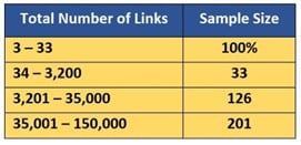
外部串扰测试的建议样本量
选择受扰链路时,请勿选择那些在连接器排末端端接的链路,因为这不是最坏的情况。受扰链路的上下方都应被连接器环绕。不过,要确保干扰源在同一电缆束中,跨电缆束的外部串扰不被视为显著影响。
与非屏蔽电缆相比,屏蔽电缆具有更强的抗噪能力,几乎不会出现外部串扰。然而,屏蔽电缆上的屏蔽层开路(未连接)会导致外部串扰测试不通过。这可能是由于屏蔽层安装不正确造成的,例如夹住了电缆箔片的非导电侧。虽然大多数测试仪检测的是主机屏蔽层和远端屏蔽层之间的简单连续性,但信号会寻找任何能到达远端的路径,包括通过配线架和机架连接的建筑物公共接地。这意味着即使屏蔽层开路,测试仪也会显示屏蔽层已连接。您可以使用 DSX CableAnalyzer™ 认证测试仪来避免这种情况,它通过专利测量技术报告屏蔽层完整性问题的距离。
如果您仍然认为可以在外部串扰测试上敷衍了事,那就再想想吧。如果规格要求或保修需要进行外部串扰测试,无论电缆是否屏蔽,您都必须按照标准建议指定样本量。如果不这样做,您就有可能需要对每条链路进行外部串扰测试,这是一个代价高昂的疏忽。
#4:测试通道而非永久链路
在网络中,通道将一个有源设备连接到另一个有源设备,包括任何跳线和设备电缆。这可能是从数据中心的接入交换机到服务器,包括交叉连接或互连处的跳线。在局域网中,这可能是从电信间的接入交换机到笔记本电脑、摄像头、Wi-Fi 接入点或其他设备,包括从交换机到配线架的跳线以及从插座到设备的设备电缆。行业标准将通道的总长度限制为 100 米,包括最长 90 米的电缆和不超过 10 米的跳线。
永久链路是通道中最长达 90 米的固定部分。它通常由数据中心从一个配线架到另一个配线架的电缆组成,或者在局域网中,是从配线架到工作区插座或整合点的电缆。

正确的数据传输依赖于通道的性能,因为它是网络上有源设备进行通信的完整端到端链路。直观来看,通道测试无疑是正确的方法,对吧?错误。
根据行业标准,使用符合标准的跳线和永久链路,通道测试总是能通过。然而,如果您仅使用高质量跳线来测试通道,永久链路可能存在的问题就无法被检测出来,而且通道日后可能无法正常工作。一旦网络投入运行,跳线通常会随着设备重新配置而移动或更换。跳线的操作和处理比其他任何组件都多,这使其更容易受损。这就是为什么跳线常被称为通道中的“最薄弱环节”。如果您最初使用高质量跳线测试通道,而后来其中一根跳线损坏或被最低标准的跳线替换,通道可能就无法通过测试了。因此,测试永久链路至关重要,它是网络的真正基础。只要在通过测试的永久链路上添加符合质量标准的跳线,通道测试最终总会通过。
这就是 DSX CableAnalyzer 测试仪配备的永久链路适配器质量极高的原因之一,它们可避免对被测永久链路产生不利影响,最终确保与符合标准的跳线的互操作性。
#5:使用错误的适配器测试 MPTL
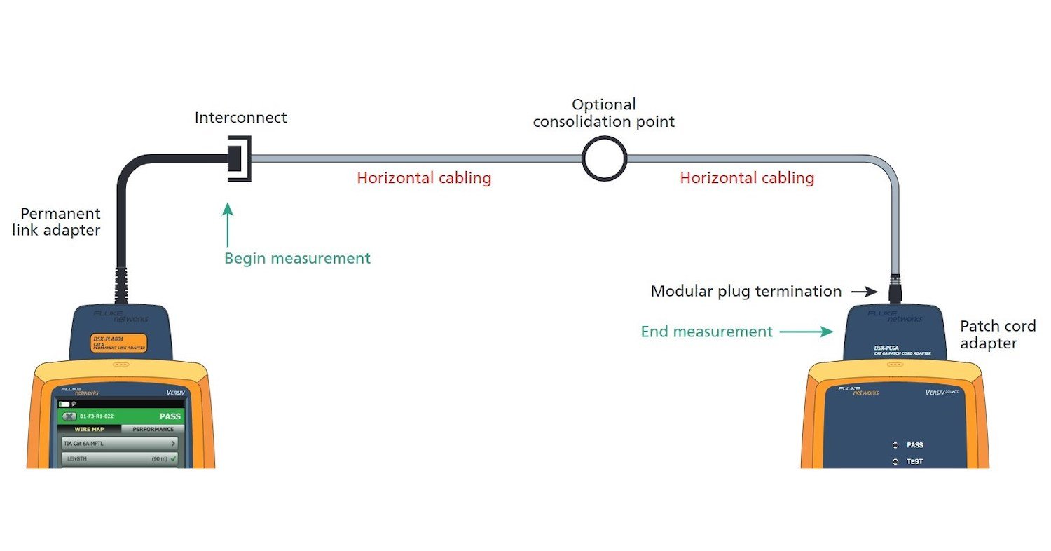
模块化插头端接链路 (MPTL) 是一种直接连接方法,其中水平电缆一端端接至插头,并直接插入设备。行业标准认可这种配置为连接设备的一种可选方式,适用于部署插座和设备电缆不切实际或不安全的情况。对于通常不需要移动的设备,如以太网供电 (PoE) 灯具和监控摄像头,这种方式也很理想。
当 MPTL 直接插入设备时,您不再拥有典型的四连接器通道,也就不能像使用两个永久链路适配器测试链路那样进行测试。然而,您也需要确保能够验证远端现场端接插头的性能。一些技术人员在远端使用了通道适配器,但这使得远端的连接未纳入测试范围,从而得出过于乐观的结果,并且可能会忽略现场端接插头存在的问题。风险在于,一旦将电缆插入设备,链路可能无法正常工作。
相反,行业标准要求在近端使用永久链路适配器,在远端使用跳线适配器,如图所示。这将确保现场端接插头的性能被纳入测试结果中。Fluke Networks 为 DSX CableAnalyzer 的永久链路适配器配备了单个跳线适配器,方便使用。只需确保在测试仪的测试限制下选择 MPTL 即可。
#6:忘记为测试结果启用绘图数据
绘图数据是认证测试所需测量测试参数的全彩图形化呈现。对于铜缆认证,绘图数据包括关键参数的图表,包括:插入损耗 (IL)、回波损耗 (RL)、近端串扰和远端串扰(NEXT、PSNEXT、PSACRN、ACRF、PSACRF),以及外部串扰(PSANEXT 和 PS AACR-F)。每个图表的纵轴(Y 轴)为分贝 (dB),横轴(X 轴)为频率。频率会根据所测试的电缆类型而有所不同:对于 5e 类电缆,最高可达 100 MHz;对于 6 类电缆,为 250 MHz;对于 6A 类电缆,为 500 MHz。请注意,您也可以扩展频率,这对于将电缆重新认证到更高标准时很有用。
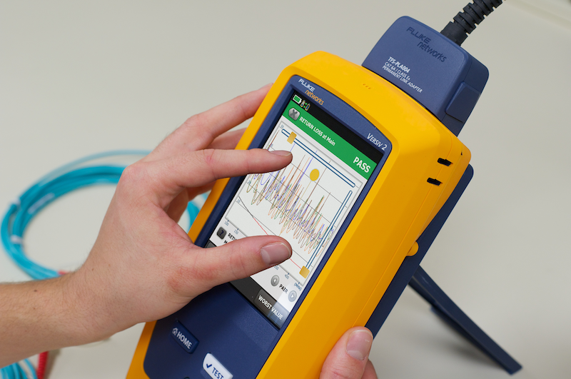
对于每个图表,平滑的红线表示您所依据标准(如 TIA、ISO/IEC 等)的测试限制。锯齿状的彩色线条表示各个线对及线对组合的测试结果。这些线条呈锯齿状,是因为实际结果往往有波峰和波谷,只要它们在限制线之上,就没有问题。

启用绘图数据至关重要,因为认证测试通常需要它,而且它能提供有关电缆内各个线对性能的有价值可视化信息。这也是真正诊断被测链路可能出现问题原因的唯一方法,因为您可以看到串扰发生的位置。您还必须在 DSX CableAnalyzer 测试仪上启用绘图数据,以包含 HDTDX(高清时域串扰)和 HDTDR(高清时域反射)参数,这些参数可显示时域信息,用于指出被测链路上串扰或回波损耗过大的位置。
如果您需要 Fluke Networks 的故障排除支持,绘图数据也是必不可少的。如果您没有可供我们技术专家分析的绘图数据,我们会要求您启用绘图数据重新测试,这会使您的测试时间翻倍。幸好,DSX CableAnalyzer 认证测试仪的默认设置是为所选测试限制要求的基于频率的测试显示并保存绘图数据。至少,我们建议保持此默认设置。选择“扩展”会保存超出所选测试限制频率范围的数据。此外,您的客户会欣赏直观的裕量显示,没有绘图数据的报告会显得空洞。
#7:忽略正确的光纤检查和清洁
尽管不断有人提醒并宣传检查光纤端面的重要性,但连接处污染仍是光纤网络出现问题和故障的首要原因。无论是在光纤交叉连接点、设备端口还是跳线末端,只要有暴露的光纤端面,就有被污染的风险,导致光纤纤芯上附着微粒,进而造成损耗和反射。在进行最终连接前,忽略或只是忘记正确检查和清洁光纤,可能会导致两种截然不同的结果:要么让客户满意并顺利开展下一项工作,要么花费额外的时间(和金钱)排查故障。
检查光纤端面时,仅用光纤显微镜进行快速人工检查是不够的。您的经验水平、环境照明、视力,甚至您的匆忙程度或疲劳状态,都会影响您准确检查光纤端面的能力。
好消息是,有一项光纤检查标准可帮助简化流程并消除人为主观因素。IEC 61300-3-35《光纤互连器件和无源元件基本测试和测量程序标准》提供了一套推荐的清洁和检查流程,其中包括基于在光纤端面关键纤芯和包层区域发现的划痕和缺陷数量及大小的特定清洁度分级标准。遵循此标准有助于避免不必要且昂贵的电缆和/或设备更换。

更好的消息是,Fluke Networks 光纤检查工具可根据 IEC 61300-3-35 标准自动给出通过/不通过结果。
#8:1 级光纤测试未使用单跳线参考
对于 1 级光纤测试,连接器损耗是指一对配对连接器的损耗。实际上,测量单个连接器的损耗是不可能的。测试一条永久光纤链路,例如从一个配线架到另一个配线架,应包括首尾两端连接器的损耗,因为布线设备在实际使用中就是这样的。为了测量这些连接器的损耗,必须使用测试参考线 (TRC) 将它们与质量类似的连接器配对。
使用 TRC 时,测试仪必须通过设置参考值来考虑 TRC 的损耗,这就好比把一个碗放在秤上,然后将秤校准为零,以便准确称量放入碗中的任何物品。行业标准推荐使用单跳线参考法来设置参考值。这使得测试能够涵盖通道两端连接点的损耗。由于信道中的大部分损耗是由这些连接造成的,单线参考法能提供最高的精度。
虽然双跳线参考法看似更合理,但这种方法会排除两根跳线之间的连接损耗,最终在损耗测量中只包含一端的连接损耗。它只能部分反映总损耗,可能会得出过于乐观甚至是负损耗的结果。双线参考法导致的负损耗会在 Fluke Networks CertiFiber Pro® 光损耗测试装置上产生警告并判定为不通过。许多布线供应商会拒绝接受采用双线参考法得出的任何结果,这可能会使您无法获得保修。
设置参考值时,CertiFiber Pro 测试仪提供了“设置参考值向导”,它通过动画一步步引导您完成整个过程。它会确切地告诉您如何将 TRC 连接到主机和远端设备。参考值设置完成后,该向导会引导您断开 TRC 与输入端口的连接。
#9:光纤测试使用错误的参考线
对光纤布线设备进行认证时,只使用测试设备制造商推荐的 TRC。真正的 TRC,比如 Fluke Networks 提供的那些,由参考级电缆和连接器构成,其损耗极低,多模低于 0.1dB,单模低于 0.2dB。非真正的 TRC 可能会导致误判不通过,这对您业务成本的影响,远远超过购买廉价替代品所节省的费用。试想一下,您可能不得不重新安装一条原本使用推荐的 TRC 就能通过测试的光纤链路。
无论使用哪种 TRC,在开始测试前验证其性能都是最佳实践。这能让您知道,当链路测试不通过时,不是 TRC 性能不佳导致的。我们建议每 288 次测试都验证 TRC 的性能并记录结果,这样您就能有一个基准来判断 TRC 是否磨损并需要更换。CertiFiber Pro 测试仪的向导会引导您完成 TRC 的验证过程。
使用正确类型的 TRC 也至关重要。对于多模光纤,行业标准要求进行环型通量 (EF) 测试,这种测试更接近当今光纤收发器的发射条件。EF 测试可减少测量不确定性,避免得出过于乐观的结果,并且是布线供应商提供保修所要求的测试。测试多模光纤时,您需要一台符合 EF 标准的测试仪,如 CertiFiber Pro OLTS,以及符合 EF 标准的 TRC。
尽管 EF 测试符合标准且是最佳实践方法,但如果您仍使用通用心轴来控制发射条件并通过去除高阶模来提高精度,那么要密切关注您的 TRC。如果您偷工减料使用普通线,它们可能是由弯曲不敏感多模光纤 (BIMMF) 制成的。由于 BIMMF 能承受更紧的弯曲且信号损耗大幅降低,将 BIMMF 测试线与心轴配合使用并不能去除高阶模。事实上,行业标准规定所有测试线都应使用非 BIMMF 光纤,即使您测试的链路使用的是 BIMMF 光纤。使用我们符合 EF 标准的非 BIMMF TRC 进行 EF 测试是一种更精确的多模光纤测试方法,这就是行业标准要求采用该方法的原因。
#10:依靠双工测试仪进行 MPO 线缆认证
数据中心中大多数高速 100 到 800 千兆光纤链路依赖多芯推拉式 (MPO) 连接器解决方案。现场测试是确保 MPO 链路符合应用性能需求的方式。用双工测试仪测试多光纤 MPO 光纤链路显然会耗费大量时间。事实上,用双工测试仪测试端接 12 芯 MPO 连接器的链路,采用三跳线法大约需要 15 个步骤,并且要使用 MPO 转 LC 扇出线缆或低损耗 MPO 转 LC 卡盒,将 12 芯光缆分离成单纤通道。
用双工测试仪测试 MPO 时,您必须首先验证并设置 SC-LC 和 LC-LC 测试参考线。然后,在连接到 MPO 上的第一对光纤之前,需要验证、设置并移除第三根 LC 测试参考线,而两端还有五对光纤需要测试。这个复杂且耗时的过程本身就更容易出现不一致的情况,并且在测试过程中更难保证所有连接器的清洁。

带有板载 MPO 连接器的测试仪解决了 MPO 测试中的复杂性、时间和不一致性问题,因此不必使用扇出线缆或卡盒。Fluke Networks MultiFiber™ Pro 光功率计具备此功能,可同时扫描所有光纤,并以易于读取的条形图显示测试结果。MultiFiber Pro 测试仪能够识别 MPO 的每个芯,提供每个芯的更精确数据并进行报告,以改进 MPO 连接器的确认和故障排除。它甚至能测试正确的极性,确保从发送器到接收器的连接连续。MultiFiber Pro 测试仪使您能够在无需预先了解链路极性的情况下,测试单个跳线、永久链路和通道的极性是否正确。
下次您认为双工测试仪足以满足 MPO 测试需求时,请记住,像 MultiFiber Pro 这样带有板载 MPO 接口的测试仪将简化测试流程,让您的测试速度提高 90%。
继续学习
最新报道 查看全部 >
双工应用中的光纤极性基础知识
2025-11-12
光缆认证测试:你真正需要关注的指标只有损耗、长度、极性(有时还包括反射)
2025-09-08
什么是 PoE 协商?
2025-06-30
网络和线缆测试终极指南
2025-05-29
Wi-Fi 7 与Wi-Fi 6:新增功能及其对您的网络的意义
2024-11-25
更多大众报道 查看全部 >
数据中心中的 MPO 及其测试方法
2025-11-18
双工应用中的光纤极性基础知识
2025-11-12
短距离单模数据中心应用:反射率成为关注焦点
2025-10-15
在 AI 数据中心环境中部署超高密度 400 和 800 千兆网络
2025-10-06
光缆认证测试:你真正需要关注的指标只有损耗、长度、极性(有时还包括反射)
2025-09-08
每位 IT 专业人员的工具包中都应配备 LinkIQ™ 测试仪的 5 大原因
2025-08-19


©2006-2021 Fluke Corporation。保留所有权利。
RM2011, 20/F, SCITECH Tower, 22 Jianguomenwai Avenue, Chaoyang District, Beijing, China
地址:北京市朝阳区建国门外大街22号赛特大厦20层2011室
联系电话:400-8103435
沪ICP备11037028号-15![]()