白皮书
OLTS 和 OTDR:完整的测试战略
下载 PDF
概述
由于数据中心和主干布线系统所需的带宽越来越高,以及服务供应商网络中新兴起低延迟 5G 和 FTTX 部署,光纤在多数网络安装中的作用越来越重要。水平布线系统中主要采用铜缆,很少有设备需要 10Gbps 速率,很多通过以太网供电 (PoE),光纤布线系统的使用量增加,速度达到 40 和 100 Gbps 及以上,需要更好的距离、抗扰度及安全性。根据最近的研究,从 2023 至 2033 年,全球光纤市场预计将从 80.7 亿美元增加到 132.6 亿美元。
 |
随着光纤部署变得司空见惯,网络所有者和技术人员越来越关注两类关键的光缆测试设备,即光损耗测试仪 (OLTS) 和光时域反射计 (OTDR)。
- OLTS 通过在一端使用光源,另一端使用功率计,为链路提供最准确的插入损耗测量,以精确测量另一端发出的光量。它要求按工业标准进行光纤测试。TIA 和 ISO 标注使用属于“1 层”描述 OLTS 测试。
- OTDR 通过将光脉冲传输到光纤中并测量每个脉冲反射的光量,表征各个焊接点和连接器的链路丢失情况。建议按工业标准进行光纤测试,这对于新兴的短距离单模应用至关重要,并且作为完整测试策略的一部分非常有价值。OTDR 和 OLTS 测试是指 TIA 标准的“2 层”测试,以及 ISO 标准中的“延伸”测试。
尽管两项仪器的测量看似类似,但是两者扮演不同但极其重要的角色。本文将介绍这些测试仪的工作原理、使用时机以及互相补充方式,以确保光纤链路的性能,最大程度提高客户满意度。
本页内容
什么是 OTDR?
与测试远端光量的 OLTS 不同,OTDR 可测量反射回光源的光量。通过计算近端和远端反射数量的差值,OTDR 可以推断出光纤中的损耗量。
OTDR 通过特制的脉冲激光二极管传输高功率光脉冲至光纤。当脉冲沿着光纤行进时,大多数光会远离光源。OTDR 中的高增益光探测器可测量从每个脉冲中反射的光。OTDR 通过上述测量方法,探测光纤中使源脉冲功率减弱或反射的事件。光纤的一般结构以及玻璃中存在的微小缺陷会导致一小部分脉冲光散射到其他方向。这种光被纤维中的杂质散射的现象被称为反向散射。
当光脉冲遇到连接、破损、破裂、接头、锐弯头或光纤末端时,会因折射率的变化而进行反射。这种反射称为 Fresnel 反射。“反射率”指的是:除背向散射以外,与源脉冲相关的反射光的量。在无源光学器件中,它以分贝 (dB) 为单位,且数值呈负值;数值越接近 0,表明反射越大、连接质量越差、损耗也越高。该测量值与回波损耗相同,以正值表示。回波损耗通过对比输入功率与输出功率,来反映信号的损耗程度;而反射则是通过对比输出功率与反射光的强度来衡量反射情况。对于反射率和回波损耗,此值与零的差值越大,则结果更好。(如需详细了解反射率和回波损耗之间的差异,请阅读什么是回波损耗?)
什么是 OLTS?
OLTS 是测试光缆布线的主要方式,它可提供最准确的方法,以判定总链路损耗。它符合行业标准,确保链路满足指定应用的损耗要求。
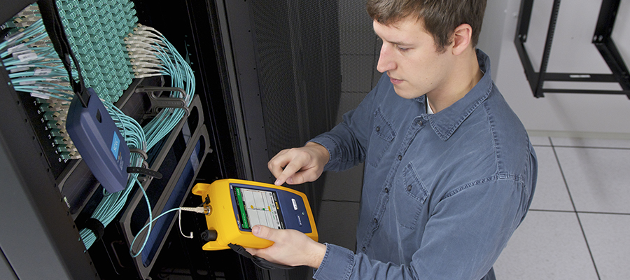
OLTS 包括光源和功率计。光源会产生特定波长的连续波,并连接至光纤的一端。光功率计采用连接在光纤链路另一端的光电探测器,该探测器会测量与光源输出波长相同的光功率。这两种设备协同工作,可确定损失的光总量。
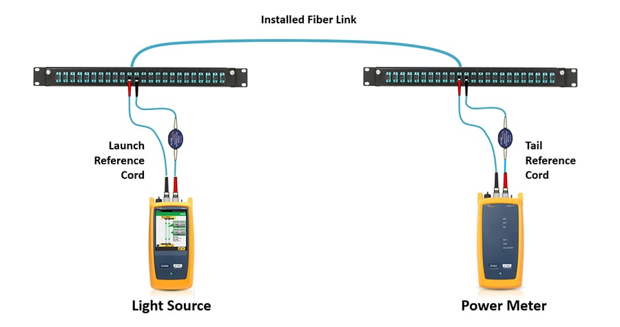 |
图 1:OLTS 测量时,在链路一端使用光源,在另一端使用功率计。CertiFiber™ Pro 等模型可通过在两端分别使用光源和功率计,同步测试两种光纤(双工),最大化测试速度。它们可共同判定链路中的光耗总量。
工业标准指定特定光纤应用的插入损耗限制,其为损耗预算和长度的组合。根据 TIA 568-3.D 和 ISO/IEC 14763-3 的 1 层光纤测试标准,OLTS 将与给定应用的损耗限制进行比较,以确定其是否通过。注意:基本光源和功率计 (LSPM) 还可根据行业标准准确测量损失,但是不包含部分关键 OLTS 测试特点,如双工测试、免提双向测试、损耗限值预加载、长度测量和其他高级功能。由于应用限值为损耗预算和最大化长度的结合,因此长度特别重要。Fluke Networks CertiFiber™ Pro 等型号可测量损耗和长度,提供清晰的通过/失败结果,确保支持相关应用场景。
 |
图 2:OLTS 提供的结果显示光纤长度(如两类光纤)以及整体光耗(dB 为单位)。
对于特性不稳定的、涉及低阶模式(在光纤纤芯附近传播的光)和高阶模式(靠近包层传播的光)的多模光纤测试,此标准要求在使用 OLTS 时使用环型通量 (EF) 光源。EF 合规光源控制进入线缆的光的模式,最终提供最精准、准确和可重复的测试结果。
此标准还建议在测试 OLTS 时使用单跳线引用方法,原因是其包含链路两端的链接插入损耗值,更精准地体现布线系统的最终使用方式。单跳线法会校准符合 EF 标准的发射光缆,校准范围从该光缆与光源的连接点,到其与光功率计的连接点。
相比之下,双跳线法会校准两根跳线之间的连接点;最终,这种方法在损耗测量中仅包含一个端接连接点,只能部分反映总损耗情况。三跳线方法引用两个连接器,排除了测试时两端连接的损耗。在某些场景下,例如你的测试设备不支持测试的链路所使用的连接器类型,将需要采用 2 跳线或三跳线校准。(有关校准设置方法的更多内容,可参阅我们的光纤测试方法解析白皮书。)
除了插入损耗之外,为什么还应测试反射率
反射率对于新型短距离单模应用变得越来越重要,如 100GBASE-DR、200GBASE-DR4 和 400GBASE-DR4。此前单模光纤应用的预算损失多于多模光纤应用——即单模 (100GBASE-LR4) 100 Gig 为 6.3 dB,多模 (100GBASE-SR4) 100 Gig 为 1.9 dB——因此新短期单模应用的使用量减少。这些新应用不仅需要更多了解低插入损耗要求,并且这些限值还取决于反射率。
多模收发器非常耐反射,但单模收发器却不能。事实上,对于高功率单模激光器,太多的反射会损坏收发器。
在新的短距离单模应用中,IEEE 根据连接的数量和反射率,指定插入损耗限值。如下图 3 所示,100GBASE-DR4 应用中有四个连接器的反射率介于 45 dB 至 55 dB 之间,插入损耗为 3.0 dB(在表格中以红色突出显示)。通过添加四种反射率介于 35 dB 至 45 dB 的连接器,插入损耗降低至 2.7 dB(在表格中以黄色突出显示)。注意:专用 OLTS 可测量反射率、最准确地测量回波损耗,其为正值。OTDR 可测量反射率,其为正数,此值由 IEEE 标准指定。
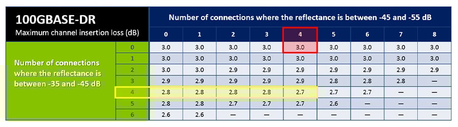 |
图 3:对于新型的短距离单模应用,IEEE 标准根据连接的数量和反射率指定插入损耗。
如何读取 OTDR 迹线
OTDR 可通过绘制反射和反向散射光,以及至光纤的路径以追踪结果,特别是在光纤链路中表征任何反射和非反射活动。
OTDR 迹线有几个常见特征:
- 多数迹线首先是一个初始输入脉冲,这个脉冲由 OTDR 连接部位发生的 Fresnel 反射产生。
- 在此脉冲之后,OTDR 迹线是一条向下倾斜的线,并被平缓的偏移中断。随着光沿着光纤传播,插入损耗或反向散射衰减会导致结果逐渐下降。这种下降可能被代表迹线在向上或向下方向上的偏差的急剧移动中断。这些偏移或点缺陷通常是连接器、焊接点或中断引起的。
- 光纤末端则显示为较大的峰(反射),后跟 Y 轴急剧下降图线。
- 最终,OTDR 迹线末端的输出脉冲是由光纤端面输出处发生的反射引起的,我们将其称之为“幽灵”活动,即技术方面而言不存在的活动。
如图 4 的迹线示例,Y 轴表示功率水平,X 轴表示距离。当您从左向右读取曲线图时,由于损耗随着距离的增加而增加,因此反向散射值会减小。解释 OTDR 迹线对新手用户来说似乎很令人却步,但实际并非如此;一些高级 OTDR 会自动解释迹线并提供详细的事件图(请参阅附录《什么是 OTDR 事件图?》)。
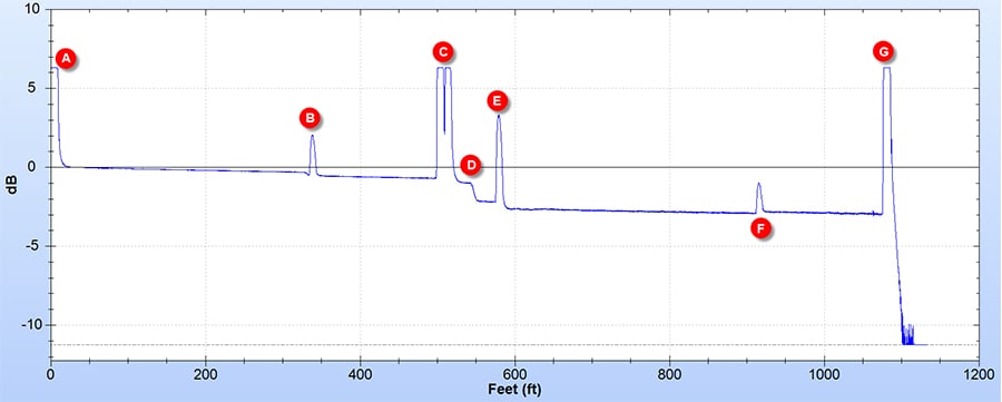 |
图 4:典型的 OTDR 迹线,显示长度、光强度逐渐减弱和事件。(A) OTDR 连接器:请注意,大反射率会导致无法分析第一个连接器的损耗特征。在此情况下,使用大约 300 英尺的发射光纤。OTDR 可据此表征 (B) 测试链路的首个连接器。(C) 显示两个与 OTDR 距离过近的连接器,以适当表征每一项的损耗。(D) 是无反射率值的损耗活动,如故障焊接点或 APC 连接器。(E) 显示一定反射率值和损耗的常见 UPC 连接器。(F) 所述为一定反射值的连接器,连接器后的信号大于以前,这通常被称为“增益事件”。这表明具有不同反向散射特性的连接光纤类型。(G) 是光纤的末端。注意:如反射率较大,则无法判定是否有连接器及性能如何,除非已连接“尾”纤。
当使用 OTDR 时,可进行双向测试,原因是指定的连接器和焊接点的损耗取决于测试方向。即使两种连接的光纤为相同类型(如 OM3、OM4 等),光纤可能会有细微变化,并且反向散射系数也不同,可能导致连接后较以前反射的光更多。如仅按一个方向执行 OTDR 测试,则可能导致比实际更小的测量损耗值,甚至是负数(这类情况被称为“增益事件”,即图 4 中的 F 事件)。与之类似的是,对于另一个较少光量方向的测试,连接后可能导致测量损耗大于实际损耗。因此 OTDR 测试双向执行,计算损耗结果的平均值,以获取更准确的结果。
当执行双向测试时,务必不断开待测试的发射和接收光纤,以在两个测试中保持相同的对齐方式并确保准确性。多亏有了 Fluke Networks OptiFiber™ Pro 这样的测试仪,使单端的双向测试变得轻松,其在双工链路远程端使用环路,自动计算两个读数的平均值,以得到最终的损耗测量值。
使用 OTDR 有哪些好处?
OTDR 通常被视为故障排除工具,对于布线系统上线后的、导致性能问题的定位活动非常重要。但是,在初始测试期间,通过 OTDR 迹线表征的整体链路可为技术人员和客户提供多种益处,并且能够发现 OLTS 可能遗漏的潜在问题。
OLTS 根据工业标准的要求,以最准确、可重复的方式计算整体链路损耗,“通过”或“失败”表示链路是否在指定应用的最大插入损耗范围内。但特定的事件损耗对 OLTS 来说完全不可见——这意味着良好的连接可以隐藏故障连接。这有何重要性?
光纤链路可能包含多个连接器和/或焊接点,通常端接和焊接点由不同的技术人员执行,部分人的技巧可能强于他人。由于技能差异或其他安装因素,链路内也可能会出现其他干扰,例如光纤端面有污迹、弯头较大和弯头较小。以 OTDR 表征光纤,可查明任何故障的位置,验证安装质量是否满足当前和未来应用的设计规格要求。它还确保不会因线缆管理不佳或安装错误而导致异常损耗事件。技术人员可查看指定连接点的表现及其在链路内的位置,以轻松识别任何存在待解决疑问的连接点,原因可能包括气隙、不良纤芯对准、缺乏清洁度或在安装过程中可能发生的其他问题。链路也有可能通过损耗测试,但由于反射问题仍然无法承载网络流量,仅 OTDR 可查找到问题。(请参阅短距离单模决定雷达的反射率,了解更多信息。)
例如,常见要求为:与焊接点关联的损耗应不大于 0.3 dB,此连接器关联的损耗应不超过制造商的规格(通常 0.2 dB 至 0.5 dB)。当今对插入损耗的要求越来越严格,错误的可能性也越来越小,因此对光纤链路中的位置和指定活动损耗的识别变得越来越重要,特别是考虑到由于电缆管理不善、连接器质量下降、光纤端面变脏,甚至由于发射机老化而导致的功率损耗,因而总损耗会随着时间的推移而增加。
通过 OTDR 表征光纤链路,也精确地确认链路内的连接数量,这是 OLTS 无法获取的信息。当需要识别链路内包含的、过多交叉连接或链路修补连接点(导致端到端链路超出指定应用的损耗限值),这非常重要。
OLTS 和 OTDR 如何协同工作
当涉及光纤测试时,如果您使用 OTDR,是否仍有必要使用 OLTS?是。
行业标准要求使用 OLTS 确保应用合规,原因是其可准确测量总光纤插入损耗。OTDR 的使用不会替代 OLTS;使用 OTDR 进行的总插入损耗测量为推断计算,不一定能描述一旦激活就将在链接上发生的总损失。特别是对于多节点光纤,当标准指定精确控制的发射条件时,OTDR 测试的准确性或可重复性不及 OLTS。
当测试或调试大量链路时,OLTS 和 OTDR 间的速度差异问题变得越来越明显。CertiFiber Pro 等高性能 OLTS 可在三秒内测量两种波长的双工链路。即使 OptiFiber Pro 等快速 OTDR 也需要至少 12 秒才可表征光纤。若要获取准确的 OTDR 测量值,必须逆向测试此光纤。OptiFiber Pro 的 SmartLoop™ 功能让这项测试更简便,但仍需额外花费 12 秒,再加上更换发射光纤的时间,因此总测试时间至少是使用 OLTS 的 10 倍。
另一方面,如使用 OLTS 且光纤链路合格时,是否需要 OTDR?此问题的答案并非如此简单。
首先,务必了解指定项目应遵循的规格。如规格书要求 OTDR 表征(TIA 标准的 2 层测试,ISO/IEC 标准的延长测试),则确实需要 OTDR 以及 OLTS 插入损耗测试。如果未指定,技术上不要求进行 OTDR 测试,但由于其在链路表征和反射率计算方面的重要价值(尤其在新兴的短距离单模光纤应用中),行业标准与专家均强烈推荐进行该项测试。事实上,光纤网络具有非常严格的损耗预算并严格控制误码超标,因此网络所有者和设计者不仅应制定总体损耗预算,还应制定每个接头和连接器的损耗、反射预算。
此外,建议在 OLTS 插入损耗测试前表征 OTDR。利用 OTDR,可测量每个焊接点和连接器的数量、位置及性能,这能让你在安装过程中、以及用 OLTS 进行最终插入损耗测试前就解决问题,而非等到网络投入运行后再处理。
此外,最终 OLTS 插入损耗测试结果是合规性明确证明所必需的。如果测试失败,并且您需要使用 OTDR 进行故障排除,您还必须使用 OLTS 再次测试。无论是否按照建议的方式使用两个测试仪,在测试之前都必须清洁和检查光纤端面(请参见附录《光纤清洁和检查的重要性》)。
集成 OLTS 和 OTDR 测试结果的优势
OLTS 和 OTDR 不仅可以相互补充以形成完整的测试方案,而且可以通过全面的记录共同帮助保护技术人员。在安装时,同时提供一份活动迹线图和一份能证明合规性的总损耗测量数据,这样一来,即便后续出现性能问题,也很难有人将责任归咎于技术人员。
当排除故障时,每个链路的记录迹线为技术人员与客户提供参考框架,以轻松、准确地识别故障和位置。例如,通过将测试过程中获取的原始迹线与新迹线进行比较,可轻松了解是否因线缆管理不佳而发生新活动,或连接点是否因污染或其他安装后的问题而导致损耗随时间增加。
当涉及选择 OLTS 和 OTDR 时,请选择易于使用的工具,且以易于理解的方式提供测试结果和报告。此外,若能通过一款测试管理与文档服务(该服务支持技术人员上传两款测试仪的结果),将两款设备的结果整合到特定项目的一份测试报告中,还能带来省时与提升准确性的双重好处。OLTS 和 OTDR 结果的集成可提供完整、全面的记录,可满足客户要求,保护技术人员,且在布线系统上线时协助进行故障排除。
OLTS 测试和 OTDR 测试不同,但却具有关键性的互补作用。了解 OLTS 测试与 OTDR 测试的差异及各自的优势十分重要,同时,认识到在光纤测试流程中二者能协同发挥互补作用,同样也很重要。而且,当将 OLTS 和 OTDR 设计为可协同工作,并能生成整合的记录化测试结果时,它们的优势会大幅增加。
附录:光纤清洁和检查的重要性
无论你仅使用 OLTS 进行第 1 层测试,还是同时使用 OLTS 和 OTDR 进行第 2 层测试或扩展测试,清洁和检查都必须是此过程的一部分。受污染的连接点仍是光纤相关问题与测试失败的首要原因;光纤纤芯上哪怕只有一个微小颗粒,都可能导致信号损耗和反射。尽管 OTDR 能检测出受污染的连接点,但在安装前清洁和检查端面可以减少测试时间并降低误差。
任何端面,即使是新品牌的连接器和工厂端接的插头和尾纤,在对接之前也要进行清洁度检查。这包括测试引线、光纤跳接线和预端接干线电缆的两端。甚至应定期检查和按需清洁测试设备上使用的可互换适配器,因为它们也可能积聚碎屑。部分制造商最近已成功改善了新工厂端接连接器的清洁度,但建议也应检查并清洁这些连接器(如有必要,即使新设备也需要清洁)。切记:即使是用于保证光纤端面的防尘罩也可能成为严重的污染源。
在检查是否需要清洁时,务必使用专门设计的光纤清洁工具,如 Fluke Networks Quick Clean™ 清洁器。对于更顽固的污染物(例如油),应使用专门为端面清洁而配制的溶剂,例如 Fluke Networks 光纤清洁笔。异丙醇 (IPA) 多年来一直被用于清洁光纤端面,但如今的专用溶剂有更低的表面张力,可以大幅提高其清除碎屑和溶解污染物的效果。IPA 干后还会留下“晕环”,这不仅会导致信号衰减,还非常难以清除。清洁后不应有溶剂留在端面上。
 |
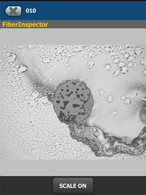 |
图 5:专用溶剂(左图)在清洁光纤端面方面的效果远优于 IPA,因为 IPA 会留下残留物(右图)。
附录:什么是 OTDR 事件映射?
当查看以图形方式显示光纤链路特性的 OTDR 迹线时,经验丰富的 OTDR 用户通常可识别发射线、连接器、机械式接续器、融合连续器、非匹配光纤,以及链路末端的反射。他们会知道,链路末端之后可见的尖峰信号是鬼影,并不是需要关注的真正事件。但是,并非所有人都是迹线分析专家,或者技术人员根本没有实践经验。
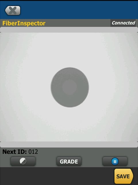
一些高级 OTDR 配备了高度成熟的逻辑,能自动解读迹线图,并生成详细的活动图形分布图,标注出连接器、焊接点以及异常点的位置。这份活动分布图对不擅长解读迹线图的人来说非常实用,同时它也能作为宝贵的培训工具,帮助技术人员提升迹线图解读能力。比如,如果技术人员不确定在迹线图上看到的是哪种类型的活动,他们可以在轨迹图和活动分布图之间来回切换,这既能帮助他们练习解读技能,也能准确验证自己看到的究竟是什么活动。
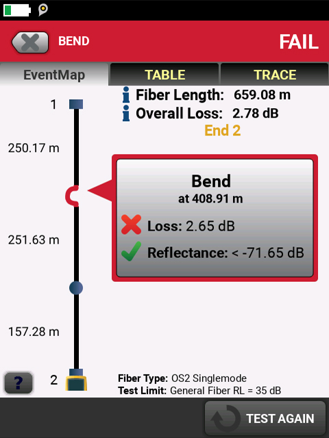 |
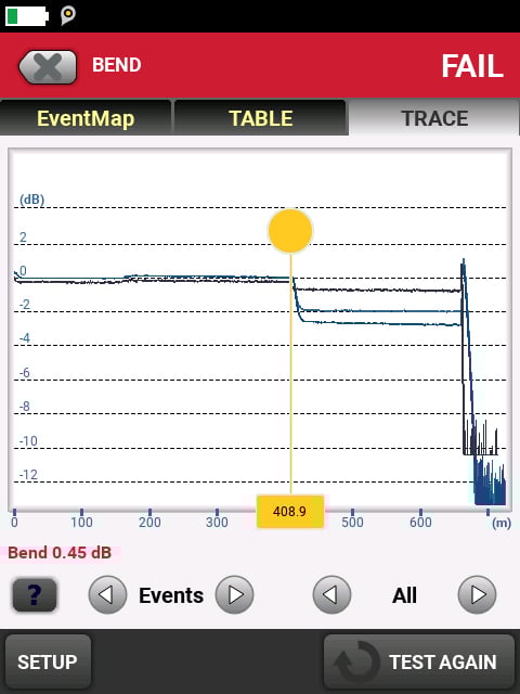 |
图 6:如右图所示,弯曲的特征是缺乏反射,在较长波长下损耗较高。高级 OTDR 可识别此类活动,并以易于解释的方式演示(左侧)。


