短距离单模数据中心应用:反射率成为关注焦点
2025 年 10 月 15 日 / 通用、安装与测试、升级与故障排除
大多数人都明白,插入损耗是光纤应用的关键参数,在损耗预算严苛的多模应用中尤为重要。从历史上看,长距离单模应用中对插入损耗的关注度较低,但短距离单模应用中已并非如此,这类应用中的损耗不仅预算更低,并且还依赖于反射率。
|
|

严苛的插入损耗预算
随着速度的提高,多模应用中的插入损耗和链路长度要求越来越苛刻。采用 400 米 OM4 多模光纤传输 10 千兆 (10GBASE-SR) 时,最大插入损耗为 2.9 dB。采用 100 米 OM4 多模光纤传输 400 千兆 (400GBASE-SR4) 时,最大插入损耗仅为 1.8 dB。相比之下,长距离单模应用的损耗预算要大得多,10 公里应用 (LR) 的损耗预算为 6.3 dB,40 公里应用 (ER) 的损耗预算为 15 至 18 dB。然而,新型短距离单模应用(DR 和 FR)的插入损耗预算更接近多模应用。而且,这些应用中不仅需要关注插入损耗,现在还需要关注反射率。
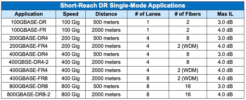
对于数据中心链路而言,由于需要由多模光纤支持超过 100 米传输距离,但又无需长距离单模应用(需使用昂贵的高功率激光收发器)所覆盖的距离,所以短距离单模应用正变得越来越受欢迎。相反,短距离单模应用采用成本更低、功率更小的收发器,可支持 500 米或 2000 米的传输距离这些经济高效的应用具有更低的插入损耗容限,详见下表。
 |
鉴于存在此类更低的插入损耗限值,多个连接点可能会造成问题。在选择单模连接时,设计人员现在就必须考虑插入损耗,并选择低损耗组件,以将总损耗控制在预算范围内。标准的 0.75 dB 连接器已无法满足需求。(简单计算便可得知:在短距离 DR 信道中,4 个 0.75 dB 连接器,再加上电缆自身的损耗会导致总损耗超出预算。)
对于这些新型短距离单模应用,您不仅需要关注其降低的损耗预算,还必须关注反射率。事实上,这类应用的插入损耗限值取决于反射率。
反射率及其对短距离单模应用的重要性
在探讨为何短距离单模应用中需关注反射率之前,我们先退一步,回顾一下反射率。
反射率用于衡量从连接器或电缆末端反射回收发器的信号功率与注入的信号功率的比值。反射率的数值始终为负值。反射率本质上与回波损耗相反,回波损耗衡量的是注入的信号功率与反射回的信号功率的比值,且回波损耗的数值始终为正值。无论是反射率还是回波损耗,数值越远离零,就越好。(请参阅插入损耗应为正数,了解更多详细信息。)
在光纤连接器处,两根光纤之间存在较小的气隙。玻璃与空气之间的折射率差异会导致光发生反射。反射还可能由多种因素导致:端面污染或抛光不良、芯体错位、光纤裂纹、光缆端面开路,以及制造过程中残留的杂质。
多模收发器非常耐反射,但单模收发器却不能,在使用更高波长的情况下尤其敏感。事实上,对于高功率单模激光器,过多的反射实际上会损坏收发器。这就是 APC 连接器在长距离单模应用中被广泛使用的原因。APC 连接器具有一个 8 度倾斜端面,可将光反射回包层,而非直接反射回收发器,从而提供更优的反射率(和回波损耗)。请注意,虽然 UPC LC 连接器也可能实现良好的反射率,但所有多纤芯的 MPO 单模连接器都必须采用 APC 设计,这是因为 MPO 连接器若使用平直的 UPC 端面,就无法实现所需的反射率。
新的反射率要求
虽然单模收发器一直容易受到反射的影响,但短距离单模应用中使用的低成本、低功耗收发器对反射更加敏感。TIA 568.3光缆布线标准规定了连接器的回波损耗(正值),但一级测试并不要求测量回波损耗。但是,IEEE 802.3 以太网应用标准规定了反射率(负值)。此外,2 级测试所要求的光时域反射计 (OTDR) 报告的是反射率,而非回波损耗。
对于短距离单模应用,电气和电子工程师协会 (IEEE) 会根据信道中的配对接头数量规定反射率。如果无法满足反射率值要求,则必须降低信道的最大插入损耗,这也使得采用 APC 连接器的必要性进一步增强。如下表所示,如果配对连接器的反射率值为 -37 dB,则短距离单模信道中只能有一个连接器。当反射率值提升至 -49 dB 时,信道中可使用 10 个连接器。
|
|

为确定信道的最大损耗,电气和电子工程师协会(IEEE) 规定了插入损耗与离散反射率值的对应关系,如下表所示。
|
|

- • 在 400GBASE-DR4 应用中,若信道包含 4 个反射率为 -50 dB 的连接器,且不存在反射率介于 -35 和 -45 之间的连接,那么其插入损耗为 3.0 dB(表格中以红色突出显示)。
- • 若这 4 个连接器的反射率均为 - 40 dB,那么最大插入损耗会降至 2.7 dB(表格中以黄色突出显示)。
- • 请记住,反射率值越远离零,反射就越好。
应当依据什么进行设计?
由于大多数单模 LC 和 MPO 连接器的反射率表现良好,约为 - 55 dB,您似乎能轻松将信道设计为 3.0 dB 的插入损耗。但请注意:在日常插拔跳线的过程中,连接器端面会逐渐附着污垢和碎屑,反射率也会随之逐渐变差。连接器在第一天的反射率为 -55 dB,并不意味着它们的反射率会永远维持在 -55 dB。光纤端面的污垢和碎屑对单模连接器而言尤其需要注意,因为单模光纤的纤芯直径要小得多:与直径 50 微米的多模光纤纤芯相比,在直径仅 9 微米的单模光纤纤芯上,一颗微小的尘埃就更容易遮挡更多光线。
即便连接器在第一天的 2 级光时域反射计测试中,反射率值为 - 55 dB,考虑到未来反射率可能升高,最好预留一定的余量。在短距离单模应用中包含 4 个连接器的场景下,这可能意味着应按 2.7 dB 的插入损耗进行设计,而非 3 dB。
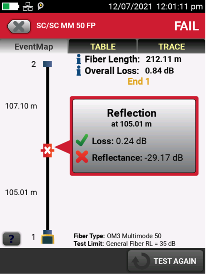
必须注意的是,即便您的链路在 1 级(插入损耗)测试中余量充足,过高的反射率仍可能会导致链路无法正常工作。这正是 Fluke Networks OptiFiber™ Pro 这类光时域反射计的用武之地——它是精准测量连接点反射率的唯一方式。OptiFiber Pro 甚至能自动解读测试结果,并在直观的图形化 EventMap 上显示所有连接点的详细反射率。
|
CertiFiber Pro 在直观的图形化 EventMap 上显示反射率值。 |
不要忘记黄金法则:检查所有连接器
对于短距离单模应用(或任何光纤应用),另一个关键考虑因素是妥善检查连接器。即便制造商宣称连接器的反射率为 - 55 dB,也不代表它开箱后就能达到这一性能水平。因此务必在连接前检查每个连接器,并在必要时进行清洁。
由于在跳线的反复插拔过程中,连接器会逐渐变脏,因此检查和清洁不应只在第一天完成——对于短距离单模应用尤其如此,因为反射性能的下降会影响插入损耗和信道的整体性能。
如果您使用 Fluke Networks FI-700 FiberInspector™ Pro 或 FI-500 FiberInspector Micro 这类解决方案来检查 APC 连接器,别忘了需要搭配 APC 探头(需单独购买)。该探头可适配 APC 连接器的 8 度倾斜角,确保能清晰观察。
最新报道 查看全部 >
光缆认证测试:你真正需要关注的指标只有损耗、长度、极性(有时还包括反射)
2025-09-08
什么是 PoE 协商?
2025-06-30
网络和线缆测试终极指南
2025-05-29
Wi-Fi 7 与Wi-Fi 6:新增功能及其对您的网络的意义
2024-11-25
更多大众报道 查看全部 >
MPOs in the Data Center and How to Test Them
2025-11-18
短距离单模数据中心应用:反射率成为关注焦点
2025-10-15
在 AI 数据中心环境中部署超高密度 400 和 800 千兆网络
2025-10-06
光缆认证测试:你真正需要关注的指标只有损耗、长度、极性(有时还包括反射)
2025-09-08
每位 IT 专业人员的工具包中都应配备 LinkIQ™ 测试仪的 5 大原因
2025-08-19


©2006-2021 Fluke Corporation。保留所有权利。
RM2011, 20/F, SCITECH Tower, 22 Jianguomenwai Avenue, Chaoyang District, Beijing, China
地址:北京市朝阳区建国门外大街22号赛特大厦20层2011室
联系电话:400-8103435
沪ICP备11037028号-15![]()